1 概念
DTS: 设备树的源文件,以 .dts 结尾.
DTSI: 设备树源文件的头文件, .dtsi 为扩展名.
DTC: 设备树的编译器,将 DTS 和 DTSI 生成 DTB 文件.
DTB: 二进制文件,以 .dtb 结尾.
Linux 内核启动的时候会在
/proc/device-tree目录下根据节点的名字创建不同的文件夹.
一般存放在 arch/<arch>/boot/dts/ 中.
编译方式.
1 | # 以 arm64 为例 |
也可以使用 dtc 直接编译.
1 | # 编译 |
2 节点介绍
2.1 根节点
根节点是整个设备树的起点.
1 | / { |
2.2 子节点
子节点是根节点的直接子项.
例如该关系图.
1 | / (根) |
1 | / { |
2.3 别名节点
aliases 节点定义了一些别名.
1 | aliases { |
2.3 CPU 节点
对于根节点,必须要有一个 cpus 的 child node 来描述系统中的 CPU 信息.
1 | / { |
2.4 Memory 节点
所有设备树文件的必备节点.
在设备树里用来描述物理内存的基地址和大小,是 Linux 内核在早期启动阶段识别内存布局的依据.
1 | / { |
2.5 chosen 节点
传递启动时的一些配置,给内核或 bootloader.
1 | chosen { |
3 属性
3.1 基本属性
compatible: 用于描述设备的兼容性信息,是一个字符串/字符串列表属性的值.
- “vendor,device”
- [“vendor,device1, vendor,device2”]
- “vendor,*”
model: 用于描述设备的型号或者名称,属性值是一个字符串.
reg: 用于在设备树中指定设备的寄存器地址和大小,address 可以是整数也可以是十六进制,size 表示寄存器的大小占用字节数.
- reg = <address size>
- reg = <address1 size1 address2 size2 …>
address-cells 和 size-cells
属性名 含义 作用对象 #address-cells地址占用的 cell 数(每 cell = 32 位) 告诉子节点:reg 的第一个部分(地址)占多少个 cell #size-cells大小占用的 cell 数(每 cell = 32 位) 告诉子节点:reg 的第二个部分(长度)占多少个 cell 每个设备节点的 reg 属性是由若干组 <address size> 对组成的,
而每一组 <address size> 的具体长度由 父节点 的
#address-cells 与 #size-cells 决定:reg = < address1 size1 address2 size2 … >
每个 address / size 占用的 cell 数由父节点规定。
如果父节点 #address-cells = <1> #size-cells = <1> => 每组是 <addr size>
如果父节点 #address-cells = <2> #size-cells = <1> => 每组是 <addr_hi addr_lo size>
如果父节点 #address-cells = <1> #size-cells = <2> => 每组是 <addr size_hi size_lo>
status: 用于指示当前设备是否可用.
值 含义 "okay"设备可用(会创建 device 并尝试匹配驱动) "ok"同 "okay"(兼容写法)"disabled"禁用设备,不会创建 device,也不会调用驱动的 probe() "fail"表示设备初始化失败(通常不用) "fail-sss"含义由厂商自定义(rare)
3.2 特殊属性
3.2.1 时钟
clock-cells: Linux 设备树中 clokc 子系统最核心的属性之一.定义该节点所代表的 时钟控制器(clock controller) 的参数个数. 用于告诉其他设备:当引用我时需要提供多少个参数.
clock-frequency: 指定时钟频率的属性. 用于指定一个固定时钟源(fixed-clock)的输出频率. 通常与 #clock-cells = <0> 一起出现.
1
2
3
4
5clk_24m: clock@0 {
compatible = "fixed-clock";
clock-frequency = <24000000>; // 24 MHz
};assigned-clocks 和 assigned-clock-rates: 前者用于在内核启动阶段强制设置某个设备所使用的时钟. 它指定设备要配置的时钟列表(引用时钟控制器 phandle). 后者与 assigned-clocks 搭配使用,指定每个被分配时钟的目标频率.
1
2
3
4
5
6
7uart0: serial@10000000 {
compatible = "ns16550a";
reg = <0x10000000 0x100>;
assigned-clocks = <&clkctrl 3>; // 使用第3路时钟
assigned-clock-rates = <48000000>; // 设置频率 48 MHz
status = "okay";
};clock-indices: 用于给时钟控制器的多个输出定义索引号(ID). 通常在 #clock-cells = <1> 的时钟控制器节点中定义,帮助驱动识别输出编号.
1
2
3
4
5
6
7
8clock-controller@10000000 {
compatible = "myvendor,myclock";
reg = <0x10000000 0x1000>;
clock-indices = <0 1 2>;
// 分别被设置为索引0, 1, 2
clock-output-names = "atlclk","aplclk","gpuclk"
};assigned-clock-parents: 指定被分配时钟的父时钟来源. 与 assigned-clocks 一起使用,控制启动时的时钟父级选择.
1
2
3// 将 clkctrl 的第 3 路时钟的父源设置为 clkpll 的第 1 路.
assigned-clocks = <&clkctrl 3>;
assigned-clock-parents = <&clkpll 1>;clocks 和 clock-names: 用于在设备节点中指定该设备所使用的时钟. 它引用一个或多个时钟控制器的 phandle 和参数.
值:<&phandle [args]> 格式
数量由设备的需要决定
参数个数由对应的时钟控制器的 #clock-cells 决定
1
2
3
4
5
6
7uart0: serial@10000000 {
compatible = "ns16550a";
reg = <0x10000000 0x100>;
clocks = <&clkctrl 0>, <&clk_24m>;
// 为设备所用的多个时钟命名,便于驱动中按名称获取,必须和 clocks 一一对应
clock-names = "bus", "xtal";
};
phandle 是设备树中用于 引用其他节点 的“句柄”或“指针”
3.2.2 中断
| 属性 | 定义位置 | 含义 / 用途 |
|---|---|---|
interrupt-controller |
中断控制器节点 | 声明此节点是中断控制器 |
#interrupt-cells |
中断控制器节点 | 定义每个中断描述所占 cell 数 |
interrupt-parent |
设备节点 | 指定中断来源的控制器 |
interrupts |
设备节点 | 描述中断号与触发类型 |
interrupt-names |
设备节点 | 命名多中断方便驱动获取 |
interrupts: 用于指定设备的中断相关信息,描述了中断控制器的类型、中断号、中断触发类型. 可以为1, 2, 3个参数
参数序号 字段名 含义 示例值 1 type 中断类型(0=SPI, 1=PPI) 0 2 id 中断号(相对该类型的编号) 33 3 flags 触发方式(电平/边沿,高/低) 4=Level High 1
2
3
4
5
6
7
8
9
10
11
12
13
14
15
16
17
18
19
20
21
22
23
24
25
26
27
28
29// 单参数
intc: interrupt-controller {
interrupt-controller;
};
uart0: serial@10000000 {
interrupts = <5>;
};
// 双参数
gpio1: gpio@48000000 {
compatible = "ti,omap4-gpio";
interrupt-controller;
};
button@0 {
interrupts = <17 1>; // GPIO17, 上升沿
};
// 三参数
gpio:gpio@fdd60000 {
...
interrupts = <GIC_SPI 33 IRQ_TYPE_LEVEL_HIGH>
...
}interrupt-controller: 用于标识当前节点所描述的设备是一个中断控制器.
interrupt-parent: 用于建立中断信号源和控制器之间的关联.
1
2
3
4
5
6
7
8
9
10
11
12intc: interrupt-controller@0 {
compatible = "riscv,cpu-intc";
interrupt-controller;
};
uart0: serial@10000000 {
compatible = "ns16550a";
reg = <0x10000000 0x100>;
interrupt-parent = <&intc>;
interrupts = <5>;
};interrupt-cells: 用于定义中断控制器(Interrupt Controller)中每个中断描述需要使用多少个 32 位单元(cell).
1 | gic: interrupt-controller@1e001000 { |
表示该节点是一个中断控制器,每个中断描述由 3 个参数组成.
1 | uart0: serial@10000000 { |
3.2.3 GPIO
| 属性名 | 定义位置 | 含义 / 作用 |
|---|---|---|
gpio-controller |
GPIO 控制器节点 | 声明该节点是 GPIO 控制器 |
#gpio-cells |
GPIO 控制器节点 | 定义每个 GPIO 引用的参数个数 |
gpios / *-gpios |
设备节点 | 引用 GPIO 控制器的引脚 |
gpio-line-names |
GPIO 控制器节点 | 给每个 GPIO 引脚命名 |
gpio-ranges |
GPIO 控制器节点 | 将 GPIO 映射到特定引脚控制器(可选) |
gpio-controller: 声明该节点是一个 GPIO 控制器.
gpio-cells: 定义了引用该 GPIO 控制器时,每个 GPIO 的描述参数数量.
- 如: #gpio-cells = <2> 则引用格式为 <&gpio_controller pin_number flags>
参数位置 名称 含义 第 1 个 pin_number GPIO 引脚号 第 2 个 flags GPIO 的极性/电平方向/中断触发配置 宏名 值 含义 GPIO_ACTIVE_HIGH0 有效电平为高(默认) GPIO_ACTIVE_LOW1 有效电平为低 GPIO_PULL_UP2 上拉(部分平台支持) GPIO_PULL_DOWN3 下拉(部分平台支持) gpio-ranges: 用于将 GPIO 控制器的编号映射到 SoC 的引脚复用控制器(pinctrl),通常用于复杂 SoC 平台,不常在简单设备中使用.
4 更多属性
Documentation/devicetree/bindings 下有着更多的属性.
通常以文档的形式(.txt, .yaml)记载属性的详细说明以及实践.
1 | jvle@jvle-ThinkPad-X1-Carbon-Gen-8:~/Desktop/works/temp/linux_files/linux-6.6.109$ ls Documentation/devicetree/bindings/ |
5 DTB 文件格式
使用 fdtdump <.dtb> 可以查看 DTB 文件的格式.
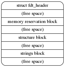
报头.
1 | struct fdt_header { |
内存保留块.
1 | struct fdt_reserve_entry { |
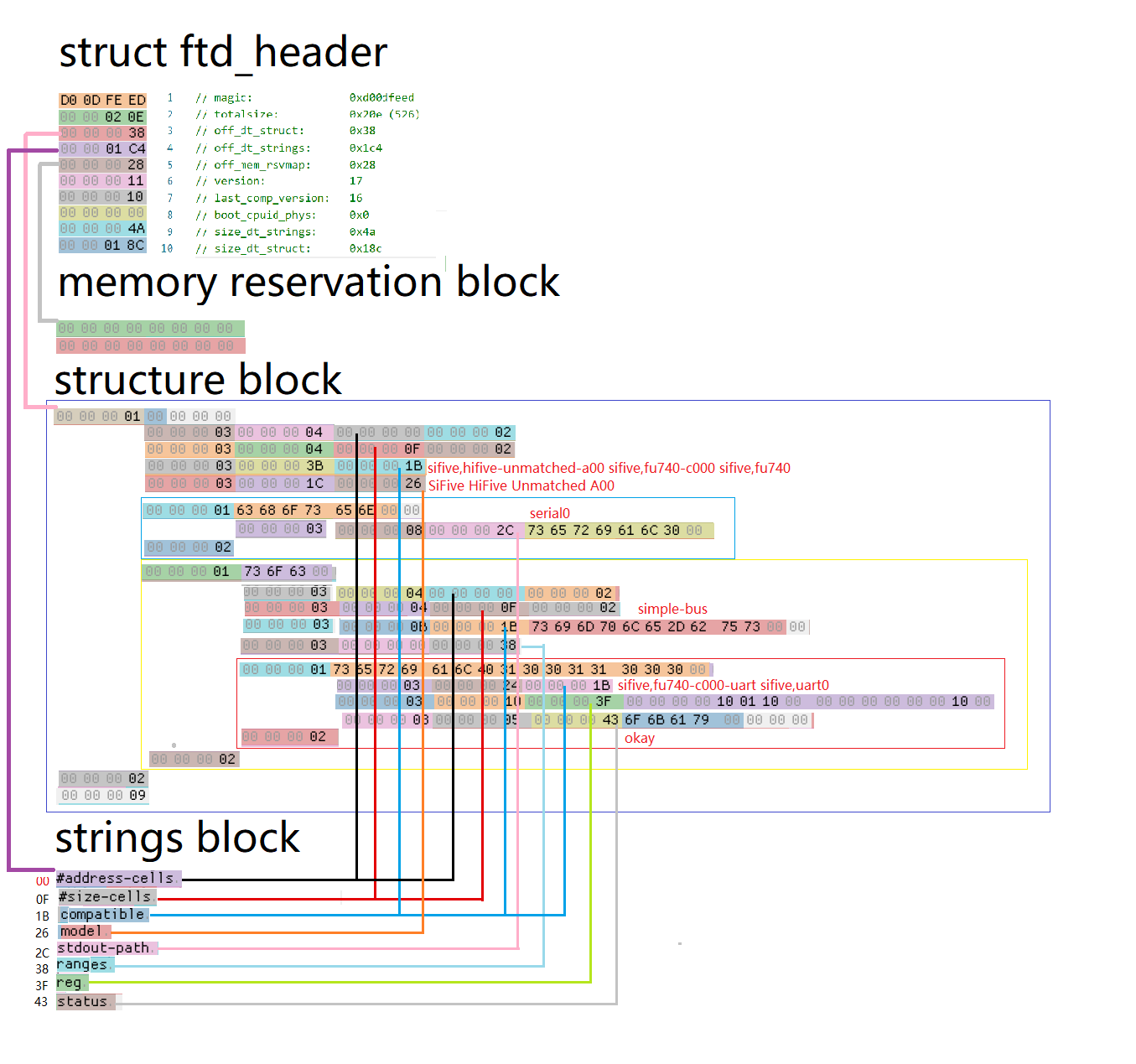
结构体块.
使用 FDT_BEGIN_NODE 表示节点的开始,然后跟上节点名字(根节点的名字用0表示),然后
使用 FDT_PROP 表示一个属性的开始(每表示一个节点,都要用0x00000003表示开始),
属性的名字和值用结构体表示.
1 | struct fdt_node_header { |
字符串块,字符串块用来存放属性的名字,比如compatible,reg等.
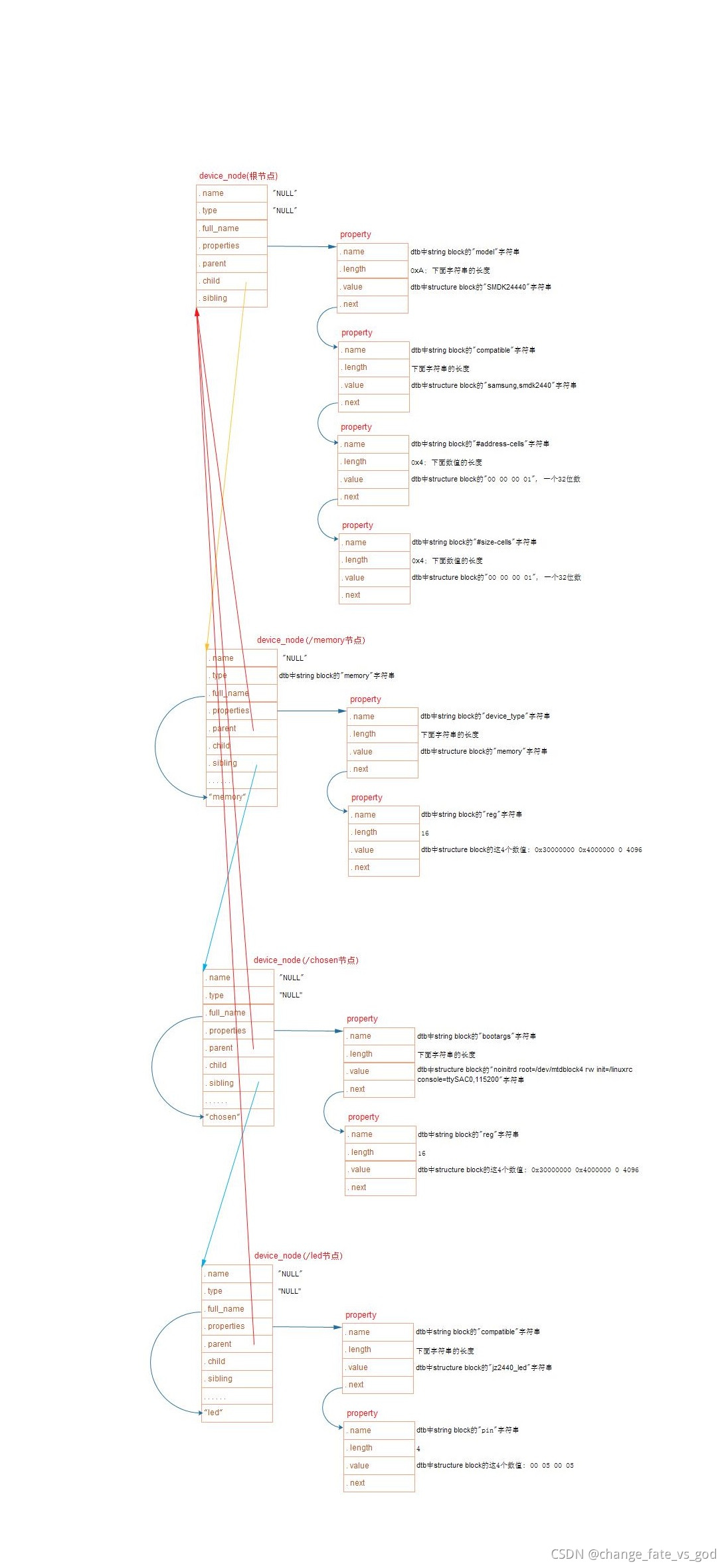
6 DTB 到 device 的转换
在系统初始化的过程中,我们需要将 DTB 转换为 device_node 的结构.
代码在 setup_arch->unflatten_device_tree.
1 | # 调用链 |
device_node 的结构如下.
每个 node 经过处理之后都会生成一个 device_node 结构体. 而 device_node 最终会被挂载到具体的 device 结构体.
1 | struct device_node { |
7 device_node 到 platform_device 的转换
device 是用 platform_device 来描述硬件资源的.
并不是所有 device_node 都会被转换为 platform_device,而转换成 platform_device 的节点可以在 /sys/bus/platform/devices 下查看.
转换规则如下.
先遍历根节点下包含
compatible属性的子节点,对于每个子节点,创建一个platform_device.遍历包含
compatible属性为simple-bus,simple-mfd或isa的节点以及他们的子节点. 如果子节点包含compatible属性值会创建一个platform_device.检查
comptaible属性是否包含arm或primecell. 如果是则不将其转换为platform_device,而是将其识别为AMBA设备.
8 OF 获取设备树节点
内核中的 of 操作函数都是来帮助我们获取到设备树中 device_node 结构体的.
of_find_node_by_name: 通过节点名称查找设备树节点
of_find_node_by_path: 通过节点路径查找设备树节点
of_get_parent: 用于获取设备树的父节点
of_get_next_child: 获取设备树的下一个子节点
of_find_compatible_node: 查找与指定
compatible匹配的节点of_find_matching_node_and_match: 根据给定的 of_device_id 匹配表匹配相应的节点
9 OF 获取中断资源
irq_of_parse_and_map: 解析设备节点的 interrupt 属性.
irq_get_trigger_type: 获取中断触发类型.
宏名 含义 数值(典型) IRQ_TYPE_NONE未定义触发方式 0x00000000 IRQ_TYPE_EDGE_RISING上升沿触发 0x00000001 IRQ_TYPE_EDGE_FALLING下降沿触发 0x00000002 IRQ_TYPE_EDGE_BOTH双边沿触发 0x00000003 IRQ_TYPE_LEVEL_HIGH高电平触发 0x00000004 IRQ_TYPE_LEVEL_LOW低电平触发 0x00000008
10 OF 获取属性
of_find_property: 查找设备树下具有指定名称的属性,并返回其结构体指针.
of_property_count_elems_of_size: 查找指定名称的属性并获取属性中元素的数量.
of_property_read_u32_index: 查找指定名称的属性,并给定索引位置处的u32类型的数值.
of_property_read_u64_index: 查找指定名称的属性,并给定索引位置处的u32类型的数值.
of_property_read_variable_u32_array: 从设备树中读取指定属性名的变长数组.
of_property_read_string: 查找指定名称的属性,并获取其字符串值.
11 OF 获取 GPIO
- of_get_named_gpio_flags: 获取设备树中配置信息指定的某一个 gpio_pin.